Trunked Radio Systems
Overview
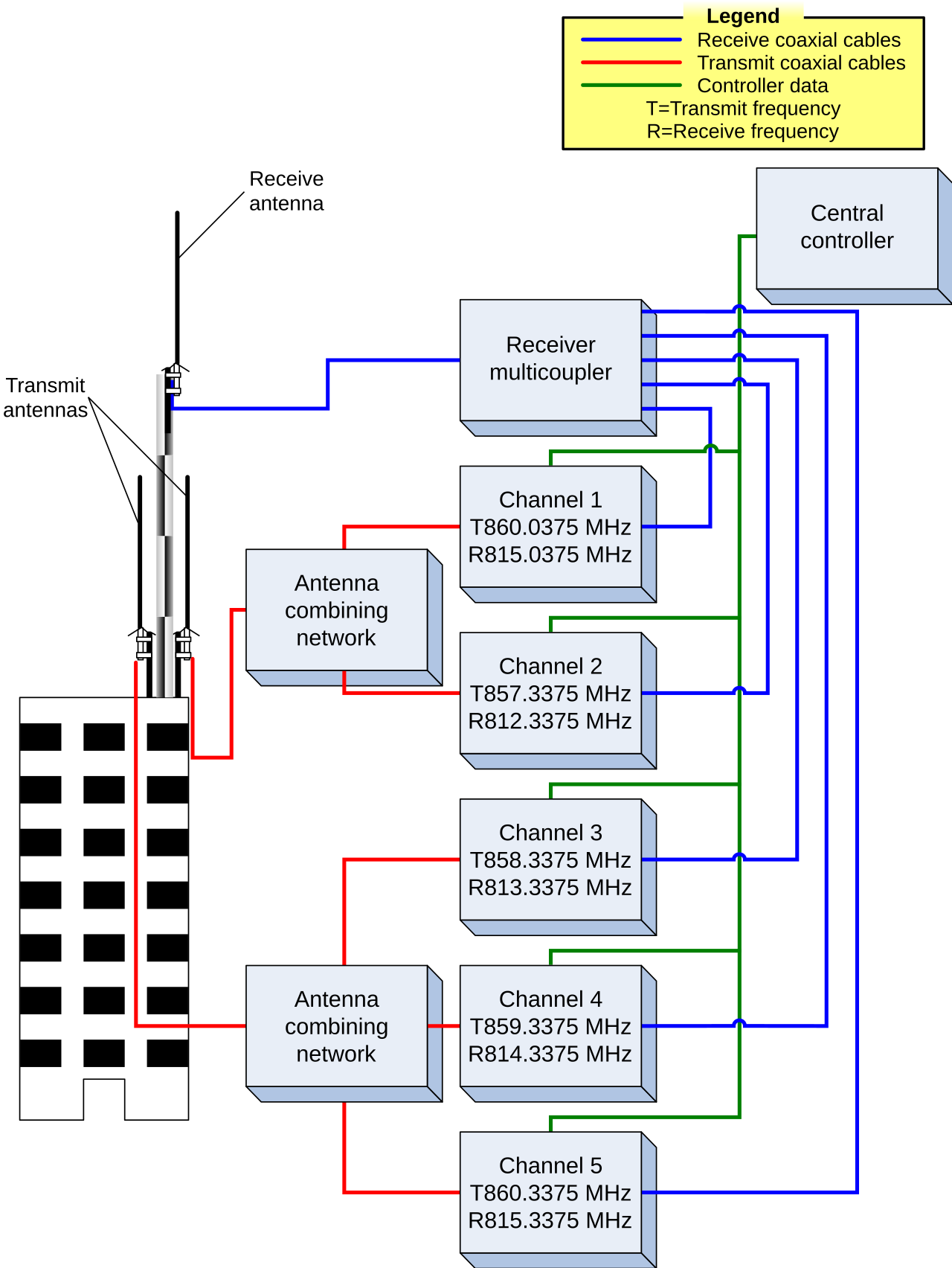
Trunked radio systems take the repeater concept from Conventional Radio Systems a step further. Instead of users manually selecting a fixed channel tied to a specific frequency pair, a radio's transmission is sent to a control station (also called a control channel), which dynamically selects an available frequency from a shared pool of frequencies and assigns the destination and channel automatically.
This dynamic allocation means many more users can share a limited number of physical channels than a conventional system could support, because a frequency is only "in use" for the duration of an individual call rather than being permanently dedicated to one user group. When a call ends, the frequency returns to the pool and becomes available for the next call.
The Control Channel: How Radios "Camp" and Get a Voice Channel
Every trunked system runs a dedicated control channel — a frequency that carries no voice at all, only data. Radios that are powered on and idle "camp" on this control channel, continuously listening to it and periodically registering their presence (and their current talkgroup affiliation) with the system controller. A trunked radio system is, in effect, a packet-switching computer network layered over RF channels: the control channel is the signaling path, and the pool of remaining frequencies are the voice/traffic channels that get assigned on demand.
When a user presses push-to-talk, the radio doesn't transmit voice immediately. Instead, it sends a request on the control channel. The system controller checks which frequency pairs are currently free, picks one, and sends a channel grant on the control channel telling the requesting radio — and every other radio currently affiliated with that talkgroup — to jump to the assigned voice channel for the duration of the call. Once the transmission ends, the participating radios return to the control channel, and the voice channel goes back into the pool, available for the next call from any group. This entire assignment cycle typically happens fast enough (well under a second) that users perceive it as a normal, if very slightly delayed, push-to-talk experience.
The whole exchange, from PTT press to voice, looks like this:
Typical elapsed time from PTT to voice is well under a second — users perceive it as a slightly delayed but normal push-to-talk.
Talkgroups vs. Conventional Channels
On a conventional radio (see Conventional Radio Systems), the channel selector on the radio maps directly to a specific frequency pair — selecting "Channel 3" always means the same repeater and transmit/receive frequencies. On a trunked radio, the channel selector instead selects a talkgroup: a logical group identity that gets transmitted to the controller on the control channel, rather than a physical frequency. The controller uses that talkgroup affiliation to decide which radios should be included when a channel grant goes out for a given call. Because the "channel" a user selects is just a software-level group identity rather than a frequency, the same physical repeater and frequency pool can carry many different talkgroups' calls, sequentially, with each call landing on whichever frequency happens to be free at that moment.
Why Trunking Increases Spectral Efficiency
Trunking's efficiency gain comes from statistical multiplexing: any one talkgroup only needs a channel for the brief duration of an individual transmission, not all the time. A conventional system must dedicate a full frequency pair to a talkgroup around the clock, even though most groups are actually transmitting only a small fraction of the time — so a large number of infrequently-used conventional channels are needed to avoid collisions between groups that rarely overlap in practice. A trunked system instead pools a smaller number of frequencies across many talkgroups, relying on the fact that not all groups will need to talk at the exact same instant, and dynamically hands out whichever channel is free. This lets a trunked system support many more users and talkgroups on the same amount of licensed spectrum than a conventional system could, at the cost of a small chance of a call being blocked (or, on systems with queuing, delayed) if every channel happens to be busy at once.
Why Trunking
Trunked systems are typically deployed by organizations that: - Have a large number of radio users relative to the number of available frequencies/channels. - Need to maximize the efficiency of a limited radio spectrum allocation. - Want features like dynamic talkgroups, priority access, and (in larger systems) call queuing rather than call blocking when the system is busy.
Motorola MOTOTRBO Trunking Options
Motorola's MOTOTRBO product line offers several trunking implementations of increasing scale and capability, all built on the same dynamic channel-pooling concept described above:
- MOTOTRBO Capacity Plus — single-site (or linked multi-site) dynamic channel pooling, aimed at large single-site or campus-style deployments.
- MOTOTRBO Linked Capacity Plus — the multi-site variant of Capacity Plus, extending it across multiple linked sites.
- MOTOTRBO Capacity Max — Motorola's largest-scale trunking architecture, adding call queuing on top of dynamic pooling for very large, multi-site operations.
Each of these builds on the shared TX/RX frequency-offset repeater fundamentals described in Conventional Radio Systems, and none of them are band-specific — they can be deployed on VHF, UHF, 800 MHz, or 900 MHz, depending on the licensed spectrum available.
Other Major Trunking Families
MOTOTRBO's trunking modes are all built on DMR, but DMR is not the only digital trunking standard in use. Two other major families, each with a different control-channel design and typical market:
- P25 (Project 25) trunking — the dominant trunked standard for North American public safety. A P25 control channel transmits continuously, and P25 trunked systems can also fall back to conventional or direct/talk-around modes as described on that page. P25's core design goal is cross-agency, cross-vendor interoperability rather than commercial/industrial efficiency.
- NXDN trunking (NXDN Type-C) — used in Icom/Kenwood NEXEDGE systems (see Kenwood NEXEDGE Overview), also uses a continuously transmitting/receiving dedicated control channel, and is common in commercial, industrial, and railroad use.
- MOTOTRBO DMR trunking (Capacity Plus / Linked Capacity Plus / Capacity Max) — unlike P25 and NXDN's continuous control channels, DMR Tier III trunking can run a control signal and a voice path on alternating time slots of the same frequency (via TDMA), letting a single physical channel carry both control and voice capacity. See TDMA vs FDMA for how DMR's time-slot approach compares to the FDMA approach used by P25 Phase 1 and NXDN.
These three families are not cross-compatible with one another at the radio level — a fleet's choice of DMR, P25, or NXDN trunking is a foundational, largely irreversible infrastructure decision.
Related Pages
- Conventional Radio Systems
- Simplex Radio Systems
- IP Site Connect
- MOTOTRBO Capacity Plus
- MOTOTRBO Linked Capacity Plus
- MOTOTRBO Capacity Max
- P25 Project 25
- NXDN Digital Standard
- TDMA vs FDMA
References
This article is part of the CTI Products Knowledge Base. Questions about RadioPro or MCN products? Call +1 (513) 595-5900 or email info@ctiproducts.com.
Informational only. This article is general background and is not engineering, safety, legal or regulatory advice. Verify requirements with the equipment manufacturer and the applicable authority before relying on it. Product names and trademarks belong to their respective owners.